
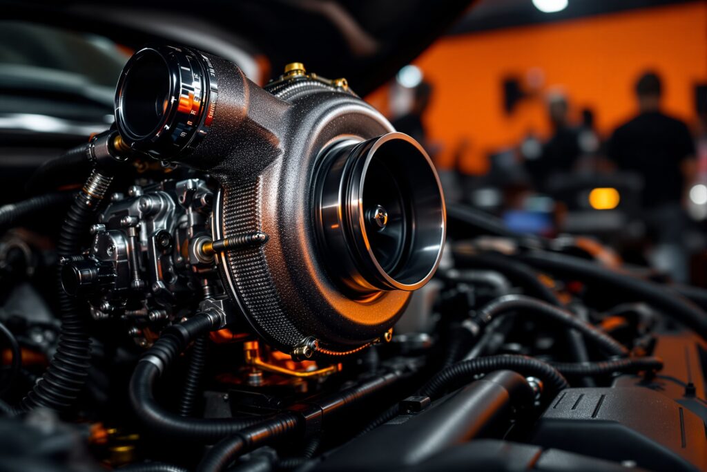
Step-by-step walkthrough for installing and configuring the M.1 Boost Controller on your turbocharged build.
Upgrading your boost management system is a highly effective way to extract reliable power from your engine. The M.1 Boost Controller offers precise pressure control, allowing your turbocharger to spool faster and hold steady boost across the entire RPM range. Taking the leap into electronic boost control might seem intimidating at first. However, a methodical approach ensures your engine remains safe while delivering the performance gains you want.
This guide covers everything necessary to successfully wire, plumb, and program the M.1 unit. By the end of this walkthrough, you will have a fully functioning electronic boost controller tailored to your specific vehicle.
Pre-Installation Requirements and Tools Needed
Before making any modifications to your engine bay, gather the right materials. Having everything within reach prevents frustrating delays during the installation process. You will need a clean, well-lit workspace and the battery disconnected to avoid electrical shorts.
Here is the basic tool list required for this job:
- Wire strippers and crimpers
- Soldering iron and heat shrink tubing (or high-quality butt connectors)
- Digital multimeter
- Silicone vacuum hose (usually 4mm or 6mm, depending on your wastegate)
- Zip ties and a mounting bracket
- Screwdrivers and a basic socket set
Verify that your M.1 Boost Controller kit includes the display unit, the electronic boost control solenoid (EBCS), the wiring harness, and the necessary vacuum fittings.
Step-by-Step Installation Guide
Installing the M.1 system requires routing electrical wires and vacuum lines. Take your time with these steps to ensure a neat, secure setup.
Mounting the Solenoid and Display
Find a suitable location in the engine bay for the boost control solenoid. It should be mounted away from extreme heat sources like the exhaust manifold or turbine housing. The firewall or a sturdy strut tower are usually excellent mounting points. Secure the solenoid using the provided bracket.
Next, mount the display unit inside the cabin. Choose a spot that is easy to read while driving but does not obstruct your view of the road. Route the wiring harness from the cabin through a factory firewall grommet into the engine bay, ensuring the wires avoid any sharp metal edges.
Plumbing the Vacuum Lines
Correct vacuum routing is critical for the M.1 controller to function. The plumbing setup depends on whether you run an internal or external wastegate.
For a standard internal wastegate setup, route a vacuum line from a high-pressure source on the turbo compressor housing to the inlet port on the solenoid. Then, run a second line from the solenoid’s outlet port directly to the wastegate actuator. Secure all hose connections with small zip ties to prevent them from popping off under heavy boost.
Wiring the System
Grab your digital multimeter to locate a reliable 12-volt switched power source. The boost controller should only receive power when the ignition is turned on. Connect the red power wire to your switched 12V source and attach the black ground wire to a clean, bare metal chassis ground. Finally, connect the harness to the solenoid in the engine bay. Double-check all crimps and soldered joints to guarantee a solid connection.
Configuring the M.1 Boost Controller for Your Build
With the physical installation out of the way, you can now power up the system and program the unit.
Setting the Base Wastegate Spring Pressure
Turn the ignition key to the ON position without starting the engine. The M.1 display should illuminate. Navigate to the setup menu and input your base wastegate spring pressure. The controller needs to know the mechanical limit of your wastegate to accurately regulate pressure above that baseline. If you are running a 7 psi spring, input that exact value into the base settings.
Dialing in Your Target Boost
Start with a conservative target boost level. If your goal is 15 psi, set your initial target slightly lower, around 12 psi, to see how the system reacts. Adjust the “Duty Cycle” or “Gain” settings incrementally. A higher duty cycle tells the solenoid to bleed off more air, which increases boost. Make small adjustments of 2 to 3 percent at a time to prevent accidental overboosting.
Safety Precautions and Testing
Taking your car out for the first test drive requires careful monitoring. Do not immediately apply full throttle.
Roll into the throttle gradually in third or fourth gear to observe the boost curve on the display. Watch your air-to-fuel ratio (AFR) gauge to ensure the engine is receiving enough fuel for the increased air volume. Listen closely for any signs of engine knock or detonation. If boost spikes past your target, lower the duty cycle immediately. Check all vacuum lines for leaks if the controller fails to reach the target pressure.
Ready to Hit the Track
Electronic boost control transforms the driving dynamics of a turbocharged vehicle. By following this M.1 setup process, you have secured a reliable and responsive system that maximizes your engine’s potential.
Keep an eye on your vacuum lines over the next few weeks, as heat cycling can sometimes loosen connections. If you plan on pushing your target boost even higher, schedule a session with a professional tuner to verify your fueling and ignition timing maps are